Micro Computed Tomography (MicroCT) for Engineering
What is MicroCT?
MicroCT is a technology which allows you to see inside an object in 3D without cutting it open. Materials with different densities can be separated, false coloured and numerically measured. Through using the latest equipment, we are able to acquire images at resolutions from 150µm down to <1µm.
Examples of MicroCT in Engineering
Case study 1: Making building materials more robust
Sym-Wall Building Technologies is an innovative manufacturer based in Nottingham. They create walls panels from a synthetic waste form of gypsum. The recycled material is taken from coal fired power stations and reprocessed through a unique automated injection moulding operation. The eco-friendly, lightweight panels can then be used as a substitute for traditional internal timber studding and plasterboard walls and are quicker to install. MicroCT was used to examine panels for voids and other defects as shown in the video below. We are working in partnership with the company to maintain panel quality.
Case study 2: Improving the accuracy of numerical predictions
In composite materials, fabric permeability plays a major role in manufacture-induced deformation of fabric reinforcements. Yet, its measurement can be controversial because the complex structure of these fabrics make the measurement or prediction of it geometry challenging. This problem leads to differing interpretations and results of permeability. MicroCT can be used to accurately measure geometry in 3D and was used to characterise a woven reinforcement. By incorporating its geometry and its local variation in simulations, fabric permeability was accurately predicted. The study also led to a greater insight into the factors that affect permeability which is leading to the manufacture of stronger woven-reinforced materials (see article for more details).
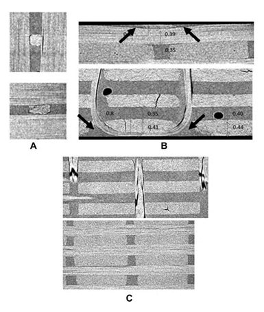
Local geometry variations observed in 3D CT images: (A) different binder cross-sections;(b) formation of dimples on surface; (C) rectangular cross-sections of warp yarns and more rounded cross-sections of weft yarns.
Reprinted from Composites: Part A, 56, Xuesen Z, Brown L, Endruweit A, Mikhail M, Long A, Geometrical modelling of 3D woven reinforcements for polymer composites: Prediction of fabric permeability and composite mechanical properties, 150-160, Copyright 2013, with permission from Elsevier.
Case study 3: Optimising the strength of multi-phase products
CT can be used to evaluate the orientation and distribution of fibres e.g. the wires in cement core below. The fibres and cement have different densities from each other and can be separated using computer software. The manufacturing process can be optimised to improve orientation and distribution to improve material strength.
Case study 4: Refining the manufacturing process of composite materials
Plant fibres such as flax are a cheaper alternative to man-made fibres. However, commercial extraction processes introduce defects that can degrade their mechanical properties. MicroCT was used in conjunction with mechanical measurements to accurately characterise the 3D fibre properties in order to compare extraction processes. This work has since led to a novel methodology which minimises fibre degradation (see the article for more details).
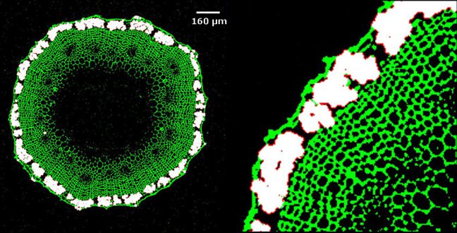
An X-ray CT image of flax stem; the image was segmented to isolate the fibre bundles for accurate measurement of the fibre cross-section area.
Reprinted from Composites: Part A, 70, Xuesen Z, Mooney S, Sturrock C, Assessing the effect of fibre extraction processes on the strength of flax fibre reinforcement, 1-7, Copyright 2015, with permission from Elsevier.
How can the technology help you?
MicroCT has a number of advantages over current methods of analysis:
- Materials can be explored visually and quantitatively in 3D, studying characteristics such as:
- Fibre orientation and distribution.
- Defect analysis e.g. bond failure, cracks (growth, interconnectivity and boundaries), porosity failure, fibre failure (separation, miss-orientation and fracture).
- Porosity/void analysis e.g. distribution/density, size and shape.
- Temporal analysis e.g. void nucleation/growth under mechanical loading.
- 3D images can be directly transformed into 3D meshes for finite element analysis or other numerical calculations.
- Quality control of assemblies in assembled states (geometry and dimensions of components may differ in assembled and unassembled state).
- Metrology e.g. CAD/CAM comparison.
Can we help you?
Using our interdisciplinary team of experts we are able to take care of the whole MicroCT data acquisition and data analysis process for you. We will take time to understand your research questions and discuss how we might be able to answer them. Through designing a customised data acquisition and image analysis package for your problem, you will obtain the best solution that X-ray micro-tomography can offer.
For more information or to discuss a new project contact Craig Sturrock: