How to build a vacuum setup
Written by: Jacqueline Arlt
February 28, 2018
Why did I want to build a vacuum setup?
My PhD project aims to explore the structure and dynamics of molecules inside liquid helium droplets. The aim of this project is to record MFPADs1 using vacuum ultraviolet (VUV) femtosecond laser pulses. Some of my colleagues are building this light source in a project running parallel to my work. The wavelength of this light source will be tunable from 130 nm to 350 nm - but what do these numbers actually mean? For comparison, the visible light spectrum ranges from about 380 nm to 770 nm2.When recording MFPADs, ion images and other data, the lower the wavelength the ‘deeper’ you can actually look into the molecule, meaning we can ‘photograph’ the molecule targeting different characteristics, for example molecular orbitals.
Our research group had an existing setup which was not being used, but was not suitable for vacuum ultraviolet (VUV) femtosecond laser pulses experiments. This setup was not appropriate for our task because we observed too much background signal in the chamber and thus in our data. This background signal is in fact dopant molecules outside the droplets which have not been effectively evacuated from our existing kit and thus contaminate our experiments. An analogy to the contamination issue is older versions of a speed camera. In this ‘old tech’, if there were two cars caught in single frame of a crime, you could not tell which car was travelling over the speed limit. In our experiment we also cannot distinguish what signal is from molecules inside helium droplets, and which signal is from molecules outside the droplets. Thus to solve our problem we must remove the ‘second car’ (molecule) from the ‘frame’, by evacuation, because it is not possible to make our laser distinguish between the molecules.
If we cannot distinguish between molecules inside a droplet and outside, why are we using the droplets at all? The answer is because they act as a nanocryostat which can cool the molecules to a temperature near absolute zero, 0.37 K (-272.78 °C). At this temperature only a few quantum states are occupied. To employ our speed camera analogy again, this means instead of acquiring a blurred image of moving car, we actually get an image with a good resolution.
The following sections show the progress we made so far in building our new/upgraded machine.
Starting Point
At first we had plenty of free space to use in our lab (Fig. 1) and the old setup (Fig. 2).
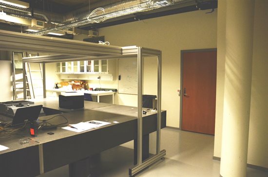
Figure 1. A lot of free space, February 2017
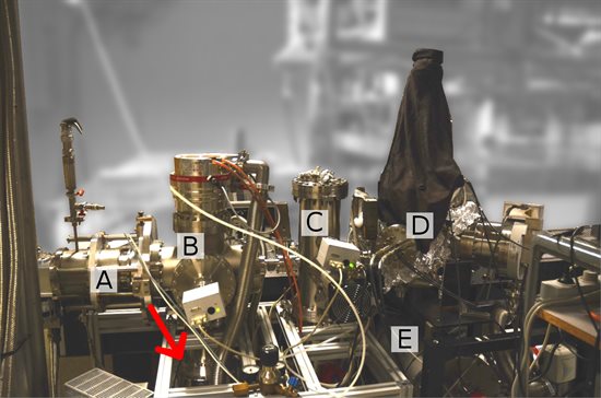
Figure 2 The old setup: A) Coldhead B) Source Chamber C) Pickup Chamber D) Target Chamber E) Supersonic Chamber, Red arrow: Adapting flange connecting the chamber with the pump, picture taken February 2017
How does the experiment work in principle? First, the coldhead (A) precools the helium gas, which has a pressure of around 25 bar, to 12-18 K (-261.5 °C to -255.15 °C). Afterwards the gas is expanded through a 5-µm nozzle.
The helium atoms coagulate to droplets in the source chamber (B). This helium droplet beam passes through a pickup chamber (C), where it is doped with molecules we wish to study.
The doped Helium beam interacts with the laser in the target chamber (D). It is often useful to compare the results we collect for molecules inside helium droplets with their equivalent ‘free gas’ molecules. Fortunately we can generate such a free gas molecule jet in the supersonic chamber (E).
The Plan
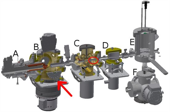
Figure 3 Autodesk Inventor Design of how the upgraded setup will look: A: Coldhead, B: Source Chamber, C: Pickup Chamber with two subsequent pickup cells D: Chamber with an additional cold trap, E: Target Chamber, F: modified old source chamber/ (new) Supersonic Chamber, Red arrow: same pump, different flange, Red circle: pickup cell
What’s the advantage of upgrading the old setup to this? We are anticipating this set-up will afford better differential pumping and thus fewer unwanted molecules will be found in the equipment. In addition we will be able to obtain ‘cleaner’ ion images. In the ‘old’ setup, a pump with a high pumping capacity was mounted on a smaller flange (Fig. 2, bottom). That meant we were wasting much of the pump’s capacity. With our ‘new’ setup, this pump is connected with a flange that has the correct size. We also have incorporated more/broader cold traps which, do as their name suggests, trap the unwanted molecules and residues of air through condensation. This is because they are filled with liquid nitrogen.
Importantly, we have reused the coldhead (A) and target chamber (D) and all pumps, gauges and valves from our ‘old’ set-up, and the source chamber (B) was modified to become the new supersonic chamber.
The chambers have been manufactured for us by an external company according to our group’s designs and specifications. These designs have been completed in partnership with a Post-Doc in my research group, and they have taken many months to complete. Predominately I have had to ensure my drawings have all the necessary information needed for the engineers to manufacture my designs, and that the specifications and tolerances were accurate to ensure all sections of the apparatus ‘fit’ together. For example, it is crucial that the helium droplet beam can travel in a straight line, not being impeded by any barrier. Therefore every specification necessary for that needs a tight tolerance, while we can put a way looser tolerance on a port meant for a window for us to look inside. Fortunately, I did not have to do all of this work on my own. I was able to discuss my designs with my colleagues, supervisor, people from our workshops and our technicians.
Other parts, like new pickup cells (where we’re actually doping the droplets with molecules) were also designed by us and constructed in-house.
In Between
The turbomolecular pumps are also referred to as ‘turbo-pumps’ and they need a pre-vacuum to work. This pre-vacuum, around 10-2 – 10-3 mbar, is provided by backing pumps. These pre-vacuum pumps are noisy and give out heat, so we located them in a cabinet or separate room away from the main equipment to avoid problems. Our turbo-pumps and backing pumps were connected by pump backing lines which had to be specifically welded for us (Fig. 4).

Figure 4. Progress to the 6th September 2017. The the pump supply lines are in the front. The only chamber installed is the target chamber. On the right side you can see a turbomolecular pump (with the red stripe). The pipes on the left are the backing lines.

Figure 5. Technical drawing of the pump supply lines. It's an overview of what we needed. You can see the planned backing lines from 3 different perspectives with a “cut-drawing” showing where we would like to have the adapters to connect the pumps with the backing lines.
Today

Figure 6. Picture taken 11th January 2018.
Fig. 6 shows an almost up-to-date picture of the setup. Today the coldhead (bottom left) is mounted. It’s wrapped up in tinfoil to keep it as clean as possible. We also wrapped the pickup chamber, the cold trap chamber and the target chamber in tinfoil for a similar reason. Underneath the foil are heating wires to “bake out” the system. By doing this, we get rid of some residues that are on the chamber walls, like water or organic residues. After such a bake-out, we are achieving a higher vacuum, typically 10-9 down to 10-10 mbar.
Personal Experience as an Early Stage Researcher
Being a PhD student, for me, means to be paid to learn and to be paid to do something I am passionate about. Sounds awesome? Well, it is. I am glad I have great colleagues in my working group, with whom I cannot only discuss research and systems, but who also have a hint or two about living in Denmark. Though it is just a few hundred kilometres north from my previous university, it is still a different country with a different culture and language after all.
Concerning ASPIRE, I can only repeat, what my fellow ESRs have reported so far: It is a great opportunity, and I enjoy the discussions with my fellow ESRs and their supervisors. I learn a lot. I am also looking forward to my secondments.
If you are also building a vacuum system and are looking for a piece of advice, get yourself a ratchet-spanner (13) and plate-nuts.
1 see Dhirendra’s ASPIRE blog article from January 2018 for more background on this area
2 Pedrotti et al. Introduction to Optics, 3rd Edition, Pearson 2014