A review on COLd Target Recoil-Ion Momentum Spectroscopy (COLTRIMS)
Written by: Giammarco Nalin
February 28, 2019

Figure 1: A sketch of a standard COLTRIMS setup. From left to right: the expansion turbopumps (with pre-vacuum), a pair of Helmholtz coils, the main chamber with electronics on top and the long molecular beam dump section. Image courtesy of RoentDek GmbH.
Introduction: why use a microscopy like this?
According to the Encyclopaedia Britannica, spectroscopy is “the study of the absorption and emission of light and other radiation by matter, as related to the dependence of these processes on the wavelength of the [incoming] radiation”. This probing approach is used vastly in a broad range of scientific research fields, from astronomy to quantum physics. Among them, molecular and atomic spectroscopy aim to investigate the composition and the physical properties of molecules and atoms in different physical phases (i.e. solid, liquid, gaseous and plasma). For these purposes, many spectroscopic techniques have been developed according to the measured variable of interest. Momentum spectroscopy is a technique extensively used in molecular (atomic) spectroscopy to detect the total multidimensional momentum of particles (i.e. cations, anions, electrons and photons). The latter arises as a consequence of ionisation processes such as electron (ion) collision or Coulomb explosion (CE). The tools used for particle detection are often called reaction microscopes (REMIs) because of their source-target interaction.
The technique presented here is called COLd Target Recoil-Ion Momentum Spectroscopy (COLTRIMS). This technique, developed during the late ’80s, gives access to “kinematically complete experiments on atomic and molecular fragmentation processes by coincident and momentum resolved detection of recoiling target ions and emitted electrons” [1]. A sketch of the COLTRIMS apparatus is depicted in figure 1. The set-up detects both the time-of-flight (tof) and the impact position of charged particles by measuring time delays using specialized devices (see the following section “The apparatus”); subsequently it computes the 3D momentum vectors of each of these particles. The target, the molecule or atom of interest, is studied in the gas phase, giving access to single molecule studies in a closed system. With this information it is possible to reconstruct one particle of a reaction (i.e. without detecting it) by exploiting the momentum conservation principle [2].
The COLTRIMS technique has been used to study atomic and molecular targets using several types of ionising sources such as ions, antiprotons, positrons and electrons for impact and, more recently, photons for photoionisation (short LASER pulses, Free Electron Laser pulses and synchrotron radiations). These ionisation sources have energies ranging from a few eV (near infrared NIR) to several keV (hard X-rays). Therefore, this technique gives access to a broad set of physical phenomena that can be studied with unprecedented precision and reliability: Compton scattering, double ionisation of atoms and molecules, ultrafast dissociation dynamics, molecular-frame angular distributions (MFPADs), photoelectron circular dichroism (PECD), and photon momentum analysis, to name a few [3].
There are several key features of this technique including:
• the use of a supersonic molecular beam capable of cooling through lamination and skimmers to narrow the velocity distribution of the target molecules
• the combination of electrical and 3D homogenous magnetic fields to catch very high energy electrons (leading to a 4pi solid angle of detection) and access time/space focussing
• micro-channel plates (MCPs) used for both amplification and time triggering signal
• the use of delay lines (DL) as position sensitive detectors (PSD)
• the coincidence detection of electrons and ions, both analogic (triggering electronic modules, old approach) or digital (made in post-analysis via software)
The apparatus: basics on the tool.
The target molecule (or an atom) is fed into the interaction area through a supersonic expansion of a pure molecular beam. A lamination expansion occurs at the nozzle, a very small aperture ranging from 5-100 um with a pressure ratio across it of at least 2. A lamination process is when increased kinetic energy and volume of the molecular beam is converted to a drop in temperature, while the enthalpy is kept constant. Therefore, the molecules in the beam gain kinetic energy and cool down to low temperature (10-1 K). Such a beam has turbulent peripheral areas, where the molecules have a broad distribution of velocities. To solve this issue skimmers (reversed funnel made of copper, with 300 um diameter small aperture) are used to ensure a very narrow Boltzmann distribution of the molecules’ (atoms’) velocities around a precise (high) value. This increases the target collimation drastically at the interaction region and the computed momentum reaches a resolution up to 0.05 a.u. (atomic units). Parameters, such as driving pressure, geometry and relative distances between the nozzle and the skimmers, can be fine-tuned to regulate the target density in the main chamber at the interaction region. This is directly related with reaction rates and, therefore to the total acquisition time, where the molecular beam crosses a photon beam.
The main chamber is kept under ultra-high vacuum (10^-10 – 10^-12 mbar) using several turbopumps in order to reduce the signal-to-noise ratio of detected signals from the residual gasses.
The core of the tool is the spectrometer, located in the main chamber. The spectrometer generates a tuneable electric field through a stack of copper-alloy plates connected by resistors and supplied by external power supplies. The geometry of the spectrometer depends on the specific experiment, but usually has an acceleration region and a drift region in which the electric field is constant or zero, respectively. Acceleration regions separate the particles according to their velocity and the drift region spreads this difference in space for detection; focusing lenses or retarding regions could be implemented for more complex time/space focusing setups.
As mentioned previously, the electric field is overlapped with a 3D homogeneous magnetic field, generated by several sets of Helmholtz coils. This approach makes it possible to catch very energetic (i.e. fast) electrons with a 4pi solid angle of detection without affecting the detection of the (heavier) ionic fragments, as shown in figure 2.
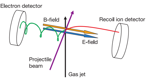
Figure 2: B and E vectors are ideally parallel; in reality, this condition can be met only in the inner part of the spectrometer (i.e. not close to the copper-alloy plates). Image reproduced with the permission of the authors from [4].
The final force acting on the charged particles is modelled according to the Lorentz’s force law (1), where E is the electrical field, B is the magnetic field and q and v are the particle charge and velocity, respectively:

At the two ends of the stack of plates, there are two detectors used to collect electrons and charged ionic fragments, respectively. In spectroscopy, depending on the variables of interest, several types of strategies have been used to collect, amplify and read the particles: Faraday cups, hemispherical analysers, channeltron/multipliers, pixel cameras, delay lines (DL), single micro-channel plates (MCPs). COLTRIMS has a combination of MCP and DL. Detectors are divided into amplification and detection regions. The amplification is simply a stack of MCPs that converts the impacting particles into electrons which multiplies at every iteration, generating a shower of electrons. These showers (with a measurable amount of electrons and a tuneable diameter of their fingerprint) impact on a set of wound wires arranged in layers called delay line (DL); these form part of the detection device. DL in the hexagonal version (most commonly used type) comprises six sets of six single wires made of copper alloy spaced 1 mm apart. Each layer has two wires kept at a slightly different potentials, one wire is called the signal and the other the reference. It is possible to obtain a better signal-to-noise ratio by subtracting the two potentials.
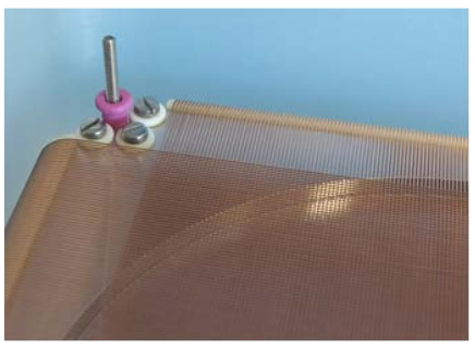
Figure 3 : Each layer has two sets of wires running parallel, called signal and reference. In the picture: the spacing in between each winding (1 mm), ceramic inserts with a pin contacts (screw) to tense the wires. Image reproduced from [5].
At the two ends of every DL, two electrical signals are created as a superimposition of all the single electrical signals resulting from the impact of the electrons from each individual shower (figure 3). The difference in travelling time between these two cumulative signals is used to compute the position of impact of each electron (figure 4); multiples of these differences for each individual shower give rise to the footprint of the whole shower and, by computing its centre of mass, an estimation of the impact position of an incoming particle with a resolution much lower than the wires’ distance (0.2 mm spatial resolution) is obtained.
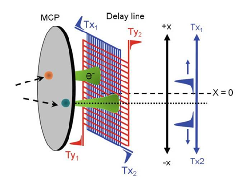
Figure 4: A sketch of the working principle of a detector (amplification with MCP and readout with DL). It has to be noticed that to fix the position on a surface at least two orthogonal set of wires are required. Hexagonal anodes with three set of wires improve the reconstruction of the signal. Image reproduced with the permission of the authors from [6].
Working principle: what is measured?
When a target atom or a molecule is irradiated with a flux of photons, one (or more) of the photons may be absorbed by the target itself. If the energy of the absorbed photon is below the binding energy of any of the electrons of the target, the absorption leads to an excited electronic configuration of the target. If the energy of the absorbed photon is equal or higher, the target relaxes, releasing energy by ejecting an electron, called a photoelectron, to the continuum. The higher the energy of the photon, the more energetic the photoelectron kinetic energy is. Photoelectrons can originate from outer (valence) shells or from more inner (core) shells. If a valence electron is ejected, it is very likely that the molecule will be simply ionised (parent ion, no break-up). If a core electron is ejected, the hole left behind could be filled by an outer electron and the excess energy can be released (with different probabilities) as photons or further electrons. If the latter case occurs, the process is called Auger decay (higher probability) [7]. As a consequence, after a few iterations, the target becomes unstable and breaks down into two (or more) charged fragments; this phenomenon is called Coulomb Explosion (CE). A CE process leads to an equal amount of electrons and fragments because of the charge conservation principle. From the absence of inter-particle interactions, achieved by the very low density of target in gas-phase, follows the momentum conservation principle; for this reason, the charged fragments are termed recoil-ions.
Personal experience as ESR in ASPIRE
It has been a privilege for me, from the very beginning, to participate in the ASPIRE International Training Network. Roentdek gave me the possibility to collaborate with a structured, large, well-prepared group such as the Reinhard Doerner group in Frankfurt; a great opportunity to gain team-working skills. I have benefitted from a continuous stream of knowledge transfer between the academic to the industrial field, learning how to be part of it. Working at Roentdek has given me the chance to be constantly exposed to cutting edge technology for particle detection and big data processing. The fruitful collaboration between the Roentdek and Doerner’s research groups has allowed me to participate and organise experiments in the most advanced light sources facilities of the world. Collaborating with the other ESR’s has made me feel part of a bigger European project.
References:
[1] Pfeifer, T. (2010, July). Quantum Dynamics and Control. Retrieved from https://www.mpi-hd.mpg.de
[2] R. Doerner et al, 2000, Physics Reports, 330, 95-192
[3] J. Ullrich et al, 2003, Rep. Prog. Phys., 66, 1463
[4] M. Schulzet al, 2003, Nature, 422, 48–50
[5] RoentDek GmbH, “MCP Delay Line Detector Manual”. Retrieved from https://www.roentdek.com
[6] McKenzie, W.R., 2010, “Focused ion beam sample ...”, Applications and Education, 1800-1810
[7] J. Viefhaus, 2005, Journal of Physics B, 38, 21